Introduction
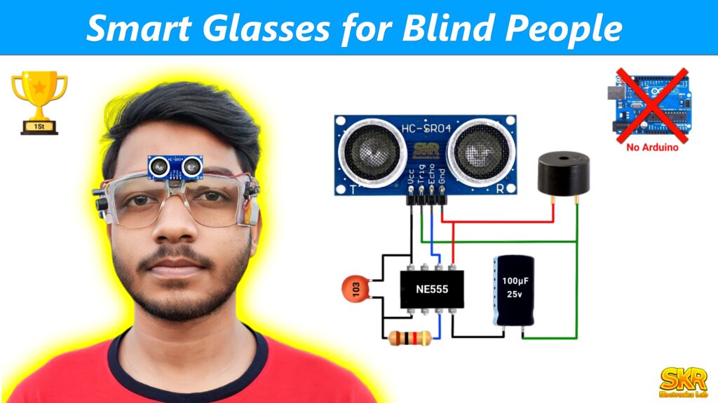
Friends, in this tutorial, I will show you how to make Smart glasses for blind people without using Arduino or any other microcontroller. This smart glasses can help blind people navigate safely by alerting them about obstacles in their way. That’s what this project is all about! Using basic electronic parts like sensors and timers, we’ve made glasses that can detect obstacles and warn the wearer with a sound. You can show this project in your school or college science project, science fair, science exhibition etc. And I hope if you show this project as inspire award project in your school or college then you will definitely get good results. I will show you how to make this project in a very simple way and also explain how the circuit works, through which you will understand the working of this project. You can easily get the components required to make this project from the offline electronic shop. And I have added the online buy link of all the components. So let’s see what components we need to make this project.
Components Required :-
1. Ultrasonic Sensor :
2. 555 IC :
https://quartzcomponents.com/products/lm555-timer-ic?sca_ref=5409384.s093ChfYYF
3. 100uF Capacitor:
https://quartzcomponents.com/products/6v-100uf-electrolytic-capacitor?sca_ref=5409384.s093ChfYYF
4. 10uF Capacitor :
https://quartzcomponents.com/products/10uf-50v-electrolytic-capacitor?sca_ref=5409384.s093ChfYYF
5. 1K Resistor :
https://quartzcomponents.com/products/1k-ohm-1-4-watt-resistor?sca_ref=5409384.s093ChfYYF
6. 10K Potentiometer :
https://quartzcomponents.com/products/10k-ohm-preset-potentiometer?sca_ref=5409384.s093ChfYYF
7. Buzzer :
https://quartzcomponents.com/products/piezo-buzzer?sca_ref=5409384.s093ChfYYF
8. 3.7V Battery:
9. TP4056 Battery charging module :
10. Switch :
https://quartzcomponents.com/products/dpdt-on-off-on-rocker-switch?sca_ref=5409384.s093ChfYYF
11. Glasses :
12. Some wire :
13. Female header pin :
https://quartzcomponents.com/products/40-pin-straight-female-berg-strips?sca_ref=5409384.s093ChfYYF
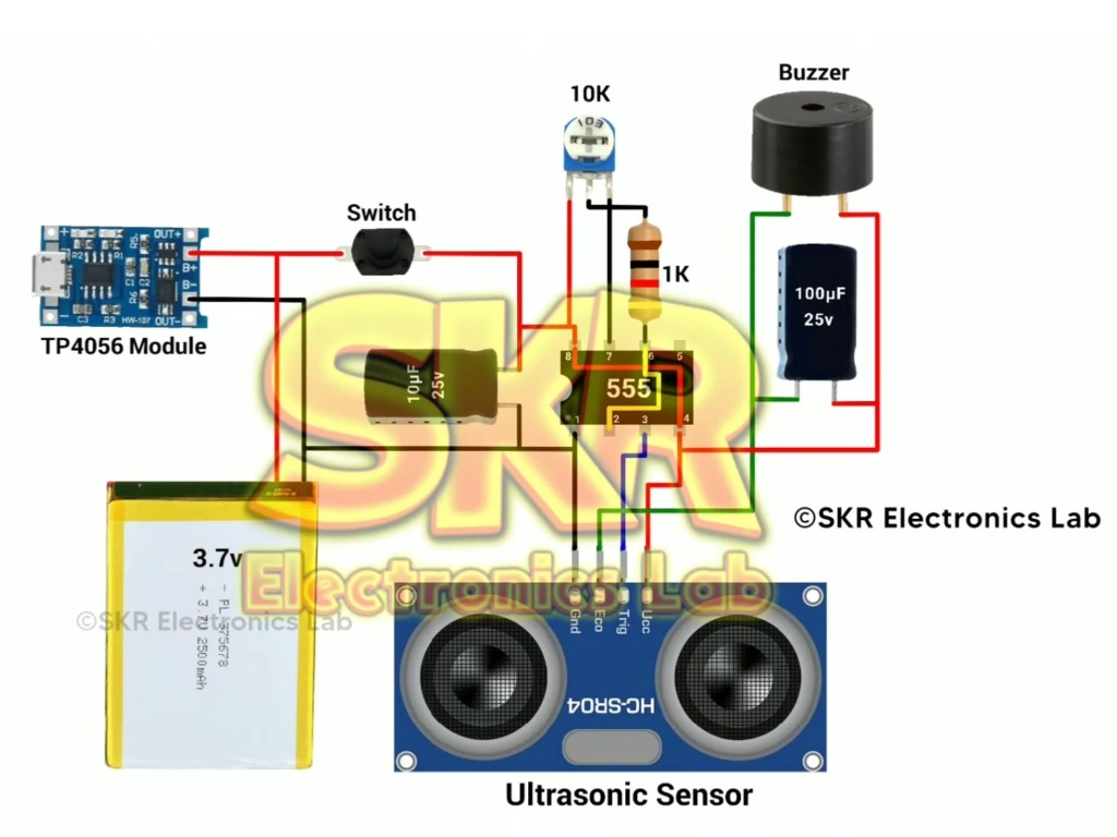
Circuit Diagram :
How the circuit works :
- Ultrasonic Sensor
The ultrasonic sensor has two parts, one part transmits the ultrasonic wave and the other part receives it. When there is no object in front of the sensor, the transmitted ultrasonic wave does not return to the receiver. And this means that there is no object in front of the sensor. But when there is an object in front of the ultrasonic sensor, The transmitted ultrasonic wave is reflected by the object and returned to the receiver, thereby indicating that there is an object in front of the sensor. This is how ultrasonic sensors works in short.
- 555 IC
The ultrasonic sensor needs a high frequency triggering signal, and the 555 IC is used to generate the high frequency triggering signal for the ultrasonic sensor.
- 10K Preset and 1K resistor
10K preset and 1K resistor form the timing components for the 555 IC. By rotating the preset, you can adjust (increase or decrease) the frequency of the output signal of the 555 IC.
- 10uF Capacitor
The 10uF capacitor which is connected between the 1 and 8 no pin of the 555 IC is used to stabilize the voltage and ensure the proper operation of the timer circuit.
- Buzzer
The buzzer is used to alert the blind person when any obstacle detected by the ultrasonic sensor.
- 100uF Capacitor
100uF capacitors connected in parallel to with the buzzer to remove any fluctuations in voltage and provide a more consistent sound output.
- Battery
The 3.7V battery is used to provide the power supply for the circuit.
- TP4056 Module
TP4056n charging module is used to charge the 3.7V battery.
- Switch
The switch is used to turn on or off the circuit.
Working in short:
- When the switch is turned on, the 555 IC starts generating a triggering signal.
- The triggering signal triggers the ultrasonic sensor and emits a high frequency ultrasonic wave.
- When any object comes in front of the ultrasonic sensor, the ultrasonic wave from the sensor will reflect on the object and return to the receiver.
- The sensor calculates the distance to the obstacle based on the time taken for the ultrasonic waves to return to the receiver.
- If an obstacle is detected within a predefined range, the echo pin of the ultrasonic sensor sends a signal to the buzzer.
- Then the buzzer starts buzzing sound to alert the blind person about the obstacle.
Overall, this projects or circuit helps the blind individuals navigate their surroundings safely by alerting them to obstacles in their path.