Introduction
Hello guys, in this tutorial, I’ll show you how to make a 360-degree fire alarm circuit and I’ll also explain how the circuit works. If you are a student and looking for a good science project for your school or college then you can make this project because this project is very easy to make and is made at very little cost. This device can detect fire from long range so you can use this project in your house for safety purpose. So, let’s see which components are required to make this project.
Components Required
Tools Required
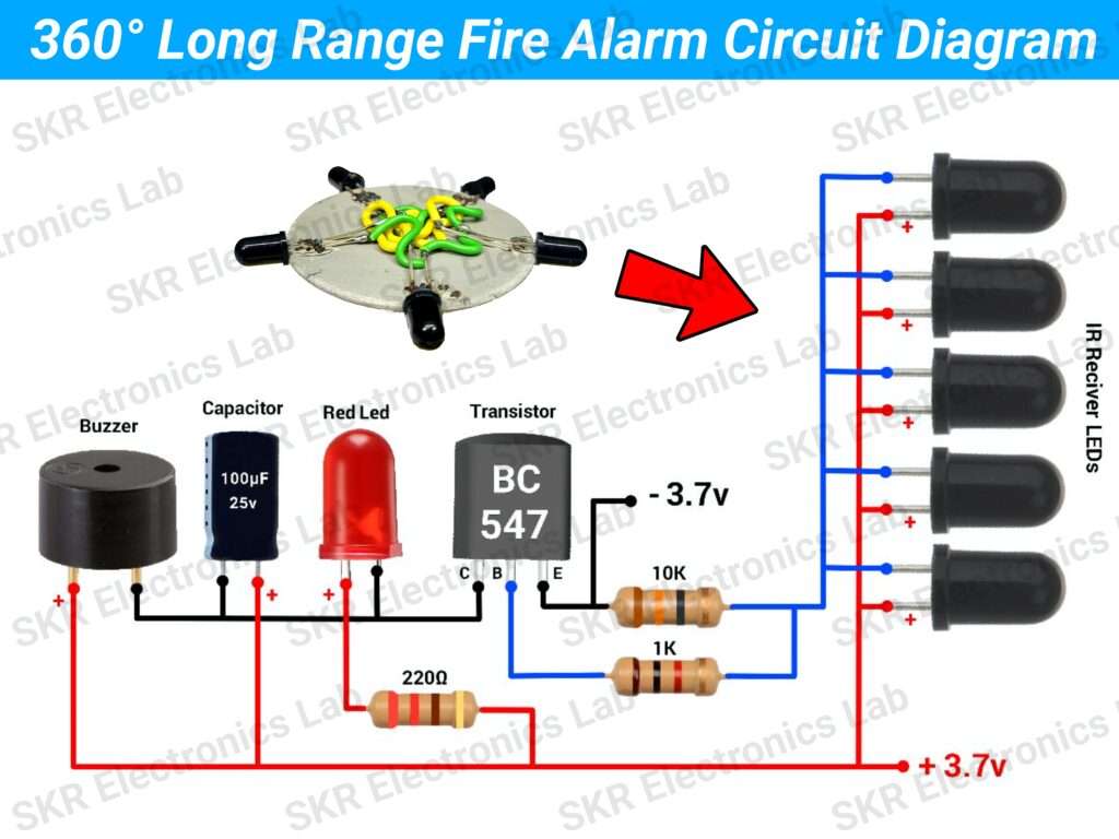
Circuit Diagram
Working Principle
let’s break down circuit working simple terms:
Power Supply
This circuity operates on 3.7V to 5V. Here I have used a 3.7V battery for the power supply but you can use a 5V mobile adaptor.
IR LED or IR Photodiode
IR LED or IR Photodiode can detect Infrared Rays and we know that fires produce far more infrared than visible-light energy. So, when fire comes in front of the IR LED it allows the flow of current through it.
Transistor (BC547) & Resistors (1K & 10K)
The transistor works as a switch in the circuit. Its base is connected through a 1K resistor to the junction of the IR photodiode and the 10K resistor. When there is no fire in front of the IR LED the 10K resistor sends a low current from the ground continuously which keeps the transistor in the off state. But when fire comes in front of the IR LED, it allows more current to flow through the base of the transistor which is greater than the 10K resistor current and that’s why it turns on the transistor.
Buzzer, Capacitor & Red LED
The Red LED is used to visually indicate the alert and the Buzzer is used to audibly alert about the fire detection. In the circuit, the LED and the buzzer negative are connected to the collector pin of the transistor, the positive of the LED is connected to the positive supply via a 220-ohm resistor, and the positive of the buzzer is connected to the positive supply directly. When the transistor turns on, it allows current to flow from the positive supply through the collector-emitter path to the ground. This completes the circuit for the red LED, the buzzer, and the capacitor (which is used for filtering the output).
This is how the circuit works.