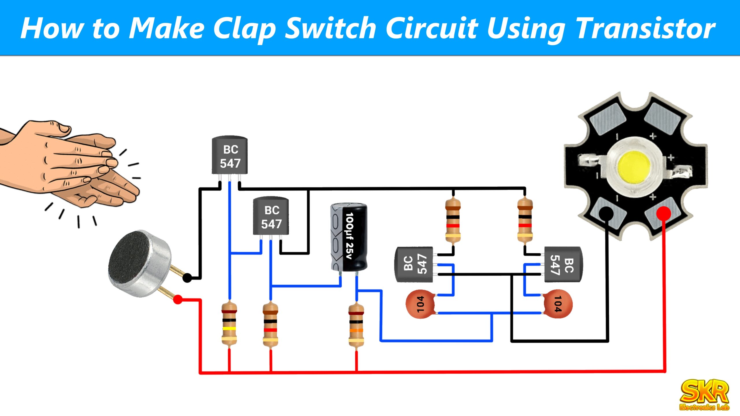
Clap Switch is a very interesting project through which you can turn on and off any AC or DC appliances (like lights, fans, TV etc.) in your home with just a clap. Clap the first time will turn the appliance on, and clap the second time will turn the appliance off. In today’s tutorial, I will show you how to make this project in a very easy and low-cost way.
Components Required:
- Microphone
- Two BC547 transistors
- 10K resistor
- 100K resistor
- 1M resistor
- 100ohm resistor
- 1μF capacitor
- CD4017 IC
- Red LED
- 9V Battery and battery cap
- Switch
- 5V Relay
- 1N4007 diode
- Breadboard or Zero PCB
Tools Required:
BC547 Transistor Pinout :

CD4017 IC Pinout :

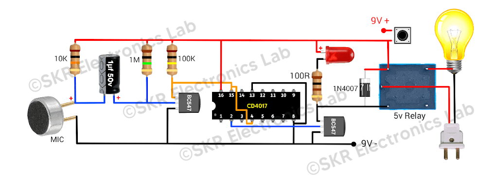
How the Circuit works :
Microphone: The microphone detects the sound of clapping and converts it from a sound signal to an electrical signal.
1μF Capacitor: This capacitor blocks the DC component from the electrical signal received from the microphone and passes this signal to the base of the transistor for amplification.
First BC547 Transistor: This transistor takes the low amplitude signal from the microphone and amplifies it and sends this amplified signal to the Clock pin (pin 14) of the CD4017 IC.
10K resistor and 1M resistor: These resistors are part of the amplifier circuit, which helps the transistor to work as an amplifier.
100K resistor : This resistor is used to keep the Clock pin of the IC always High. This resistor help to generate the clock pulse.
CD4017 IC: CD4017 IC have 10 output pins, When the first clock pulse is applied to pin 14, the output of this IC goes from 0 to 1, and when the next clock pulse is given, the output goes from 1 to 2. This is how the IC works.
Red LED: We will connect a 100ohm resistor in series with its positive pin, and we will connect the resistor to the 2nd pin of the IC and connect the negative pin to the GND, as a result when the output comes to the 2nd pin the LED will glow.
100-Ohm Resistor: This resistor is used to protect the LED from burning.
Second BC547 Transistor: This transistor is used to control the relay. When the output pin 2 of CD4017 IC becomes High, this transistor will turn on and the relay will also turn on.
5V Relay: The relay is an electromagnetic switch. When activated by the second transistor, it turns the connected load on or off.
1N4007 Diode: This diode is connected across the relay coil to protect other components from voltage spikes when the relay closes.
Switch: This switch is used to turn the circuit on or off.
9V Battery : Power source for the circuit.
In short –
When we clap the microphone detect the sound and convert the sound signal to an electrical signal and fed this signal to the base of the BC547 transistor, this transistor amplifies the signal and fed the amplified signal to the clock pin of the CD4017 IC.
CD4017 IC have 10 output pins, When the first clock pulse is applied to pin 14, the output of this IC goes from 0 to 1, and when the next clock pulse is given, the output goes from 1 to 2. This is how the IC works.
We want to turn on/off an LED and transistor so we need two outputs, so we will connect output 2 of the IC to reset pin 15. As a result, when the first clock pulse is received, the output of the IC will go from 0 to 1, and when the second clock pulse is given, the output will go from 1 to 2. Whenever pin 2 goes high, the IC will reset and the output will go back to 0. We will connect the LED and the transistor to output no.1. This will cause output 1 to go high when we first clap, and the LED and transistor will turn on. And when we next clap, then pin no 0 will go high and output no 1 will go low and the LED and transistor will turn off. This transistor will control the relay, when the transistor is on, the relay will be on and when the transistor is off, the relay will be off. A relay actually works like a switch, so we can turn on or off any AC or DC appliance’s like light, fan, TV etc. by connecting it to the relay.