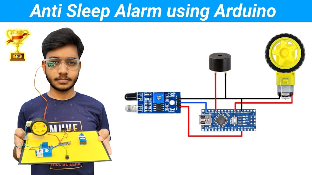
Introduction
Hello friends, in today's tutorial I will teach you how to make a laser security alarm system. Before this, you may have seen many laser security alarm tutorials.But this laser security alarm system will be different and advanced from them. In all the laser security alarm systems that you have seen before, When any object pass from the laser security alarm the buzzer beeps for few seconds and when it passed the buzzer stop beeping and this is a very big disadvantage of it. To overcome this problem I made a advanced laser security alarm system which will beep continuously after any object pass from the lase. The amazing thing is that I didn't used Arduino or any other microcontroller or IC to make this project. I just used some basics components to make this project, which you can buy easily from your local market and if you want to buy the components online then you can buy online I have provided the buy link also. So let's see which components are required to make this project.
Components Required
- BC547 Transistor
Best Buy Link : Buy
Amazon Buy Link : Buy - LDR Sensor
Best Buy Link : Buy
Amazon Buy Link : Buy - PC817 Optocoupler
Best Buy Link : Buy
Amazon Buy Link : Buy - 5mm Red LED
Best Buy Link : Buy
Amazon Buy Link : Buy - 5V Active Buzzer
Best Buy Link : Buy
Amazon Buy Link : Buy - 100R Resistor ( 2 Piece)
Best Buy Link : Buy
Amazon Buy Link : Buy - 1K Resistor
Best Buy Link : Buy
Amazon Buy Link : Buy - 6.8K Resistor
Best Buy Link : Buy
Amazon Buy Link : Buy - Push Button
Best Buy Link : Buy
Amazon Buy Link : Buy - ON/OFF Switch
Best Buy Link : Buy
Amazon Buy Link : Buy - 3.7V Battery
Best Buy Link : Buy
Amazon Buy Link : Buy - Battery Holder
Best Buy Link : Buy
Amazon Buy Link : Buy - Battery Charging Module
Best Buy Link : Buy
Amazon Buy Link : Buy
Tools Required
Circuit Diagram
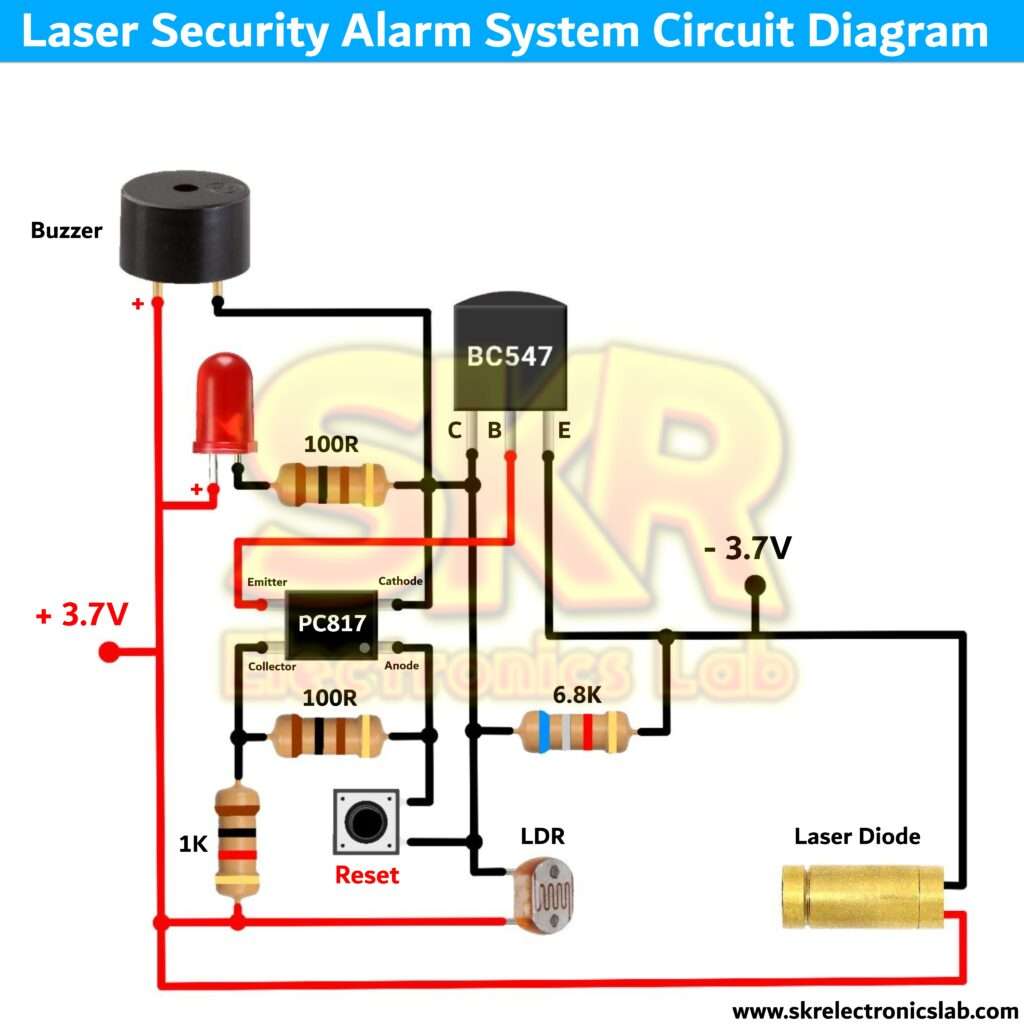
How The Circuit Works
To understand the working of the circuit we need to undesrtand the working and usage of some components.
Transistor wokring in short
BJT (Bipolar Junction Transistor) are mainly two types - NPN and PNP. Transistor has three pins - Collector, Base, and Emitter. So, for NPN Transistor The pins will be like this - Collector (Negative), Base(Positive), and Emitter (Negative). For PNP transistor the pons will be like this - Collector (Positive), Base(Negative), and Emitter (Positive).
We always connect the emitter pin tothe supply (for NPN transistorwe connect the emitter pin tonegative supply and for PNP transistor we connect the emitter pin tothe positive supply) and Collector pin with the load (e.g - LED, Motor etc.). Now if we provide a small amount of cureent (positive for NPN and negative for PNP) at the base pin of the transistor it will start flowing current from emitter to the collector pin. Let's try to understand why we use transistor, We use transistor for amplification or switiching purpos. Some device or circuit give us a very low output current by which we can't runa LED or Motor or any other load properly to overcome this probleme we use transistor. Because if we provide a small amount of current to the base pin it will start flowing a a high amount of current (supply) from emitter to collector. I think you understand why we use transistor and how to use it. In our circuit we have used BC547 named NPN type transistor.
Optocoupler working in short
It's an electronic component, which can transfer signal from one circuit to another without any physical connection. It has three four pins - Anode, Cathode, Emitter, and Collector.

A optocoupler consists of two components - LED and Photodetector. If we provide supply to the LED then the photodetector will allow the current flow from emitter to the collector pin. That means if we provide the input siganl to the LED we will get the same signalat the collector pin of the photodetector without any physical connection. This is how a optocoupler works.
LDR working in short

LDR ( Light Dependent Resistor ) is a type of sensor which has a resistance which varies according to the amount of light falling on its surface. It's resistance decreases with the increase in the intensity of light.
Now we will understand the working of the circuit
Let's start with the transistor BC547. We have connected the emitter terminal to the supply negative and collector terminal to the buzzer negative, LED negative (100 Ohm resistor is used to protect the LED from burn due to high current) and some components (I'll explain later). The positive terminal of the LED and buzzer is connected to the positive supply. Now if we provide a small amount of positive current to the base terminal of the transistor it will allow the current to flow from emitter to the collector terminal which will turn on the LED and the buzzer.
We are providing the positive supply to the transistor base pin through the optocopupler. To turn on the optocoupler we have provide supply the optocoupler LED side means - cathode and anode. So we are providing the negative supply through a 6.8K resistor and provioding positive supply through the 1K and 100Ohm resistor. Now if we provide supply the optocoupler will be on and the optocoupler will turn on the transistor and the transistor will turn on the buzzer and LED. But we have connected a LDR sensor between the cathode pin of the optocoupler and positive supply. As we learned from the above explanation that if light falls on the LDR it will decrease it'sresistance itself and if no light then it increase it's resistance. So when the laser beam fall on the LDR the LDR resistance become very very lower and due to this the cathode point of the optocoupler becomes positive which turns of the optocoupler (both terminal becomes positive). Because LDR resistance becomes lower than the 6.8K resistor. And if we cut the laser beam means there is no light in front of the LDR sensor so it turns on the optocoupler and it turns on the LED and buzzer.
I know you're thinking that if the laser beam fall again on the LDR then the buzzer and the LED will be off. But no it won't happen because - now the cathode pin of the optocoupler is getting current from the collector pin of the transistor and if the light fall again on the LDR the LDR resistance will be decrease but it will be grater than the resistance between emitter and collector pin of the transistor so the LDR will fail to turn off the optocoupler and the buzzer and the LED will on continiously. To reset the circuit we have connected a push button between the two terminal of the optocoupler. So when we will press the button the optocouplerwill be off and it will turn off the transistor and the system will be reset. This is how the whole circuit works. If you have any doubt's then please comment down and wewill clear your doubt's soon. Thank you for reading, have a nice day.