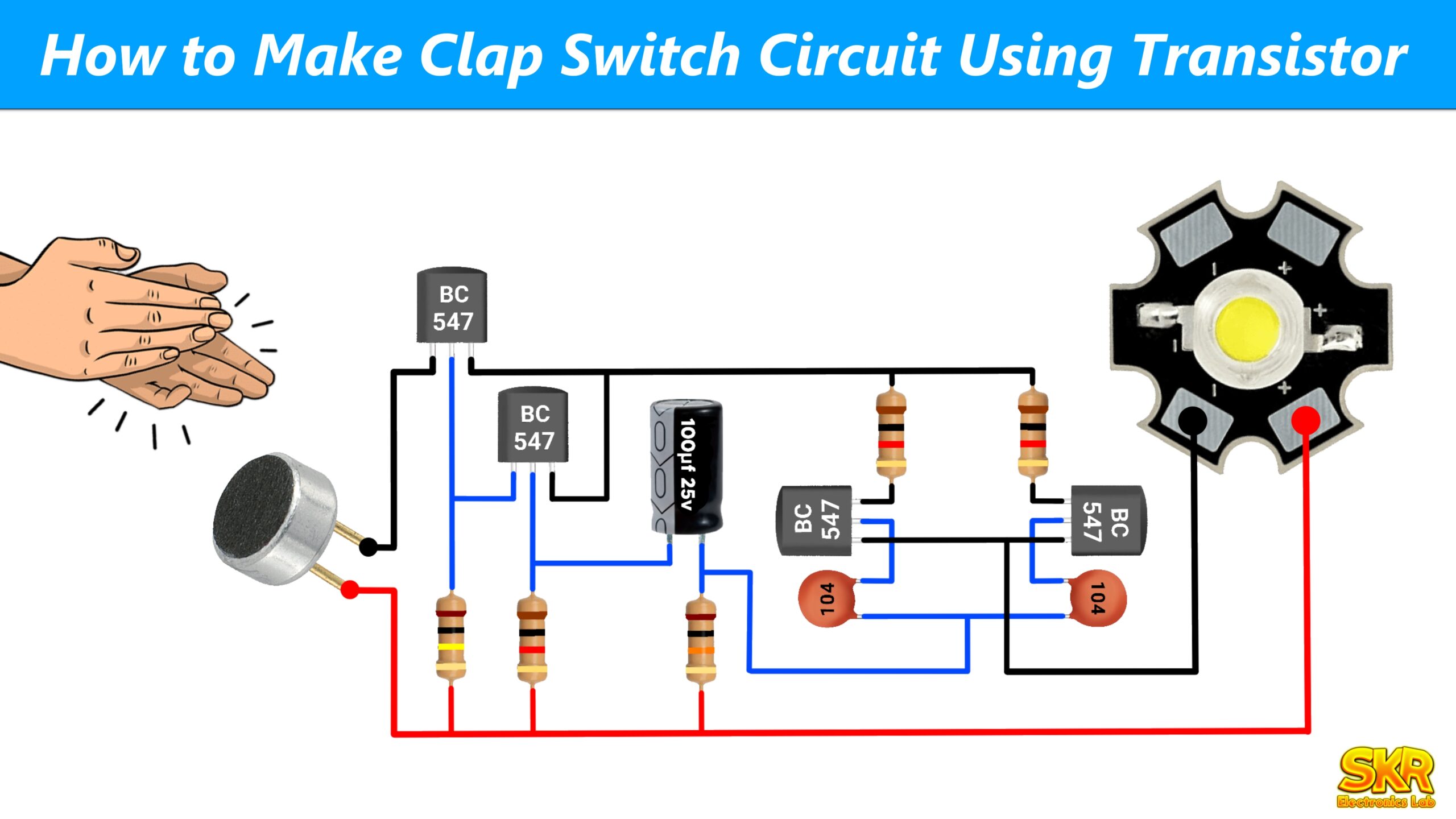
Introduction
Have you ever dreamed of controlling your home appliances like Fan, Light, TV through the Clap of your hands? Well, dream no more because today we are going to show you how to make a Clap Switch at your home. You can show this project as a school science or college science project or science fair. If you are a beginner in electronics or if you don’t have much idea about electronics, you can also make it very easily at your home just through our tutorial. The interesting thing is that we will not use Arduino or any microcontroller or any IC to make this project. We will use some simple electronic components to make the circuit, which you can easily get from local offline market at very low price. And if you want to buy components online then I have attached best buy link with component list below you can buy the components from there. So let’s see what components and tools we need to make this circuit.
Components Required
- BC547 × 5 Pieces ---> Buy Now
- Microphone × 1 Pieces ---> Buy Now
- 1N4148 Diode × 2 pieces ---> Buy Now
- 104 PF Ceramic Capacitor × 3 pieces ---> Buy Now
- 1μF Capacitor × 1 Pieces ---> Buy Now
- 1K Resistor × 4 Pieces ---> Buy Now
- 10K Resistor × 4 Pieces ---> Buy Now
- 1M Resistor × 3 Pieces ---> Buy Now
- 100R Resistor × 1 Pieces ---> Buy Now
- Switch × 1 Pieces ---> Buy Now
- 3.7V Battery × 2 Pieces ---> Buy Now
- 3.7V Battery Holder × 1 Pieces ---> Buy Now
Components for the Relay Circuit
Tools Required
Circuit Diagram

Now solder all the according to the circuit diagram. I have soldered all the components. And my circuit is look like this

You can watch our YouTube tutorial video to make the circuit like this. Now you can turn ON or OFF the output LED by Clap.
If you want to control any AC Appliances like Light or FAN through this circuit then you have to connect a relay with the circuit. If you don't have much knowledge about electronics or if you are a beginner in electronics then please don't make relay circuit. Because we will be working with high voltage here. So a small mistake can cause a big accident. And if you have good knowledge about electronics then you can make relay circuit.
Relay Circuit

–
Connect the relay and the diode according to the above diagram. Now you can controlyour AC appliances by yours hand’s clap.
Working of the Circuit
Block Diagram

1. Sound Source :
The sound source can be any but we are preferring clap sound for this circuit because clap makes a loud sound which the circuit can detect very easily. You can also trigger or turn the circuit on or off by making a loud sound like talking loudly, playing a whistle etc.
2. Microphone :
The microphone captures sound waves from the environment, including claps. When someone claps, the microphone converts the sound waves into electrical signals, which serve as the input for the circuit.
3. Microphone Amplifier :
The electrical signals generated by the microphone are very weak and may not be sufficient for proper functioning of the circuit. Therefore, the signals are passed through a microphone amplifier, which increases the strength and magnitude of the signals. This amplification process ensures that the signals are robust enough for further processing in the circuit.
4. Bistable Multivibrator :
The bistable multivibrator plays a critical role in this circuit, it can be called as the brain of this circuit. It controlling the output of the circuit based on the input signal which is received from the microphone amplifier. This part is like a flip flop, having two stable states. It consists of two transistors that are cross-coupled, meaning they influence each other’s behavior. Each transistor can be in one of two states: cut-off (off) or saturation (on). When one transistor is off, the other is on, and vice versa, making it bistable.The bistable circuit can stay in either state until it receives a trigger pulse. We can take the output from any one of the two transistors.
5. Output :
The output signal obtained from bistable multivibrator is very weak due to which we cannot control any LED or relay by this signal. So to increase the strength of the signal we will amplify the output signal through a transistor. And we can control any DC Led (less than the supply voltage) from the amplified output signal. If you want to control any AC Appliances like – TV, Light, Fan etc then you can connect relay to the output of the circuit. Through which you can easily control any AC Appliances.
Overall Operation
– When you clapped, the microphone picks the sound and converted it into an electrical signal.
– The mic amplifier boosts this signal.
– The amplified signal triggers the bistable multivibrator, causing it to switch states.
– Depending on the state of the bistable multivibrator, it either turns on or off the connected DC LED.
– By replacing the LED with a relay, you can control AC appliances (like fan or LED Bulb)
Hope you like the tutorial, If you have any doubt related to this tutorial then you can comment, I will help you.
Thanks for reading this tutorial, have a nice day.

