Introduction
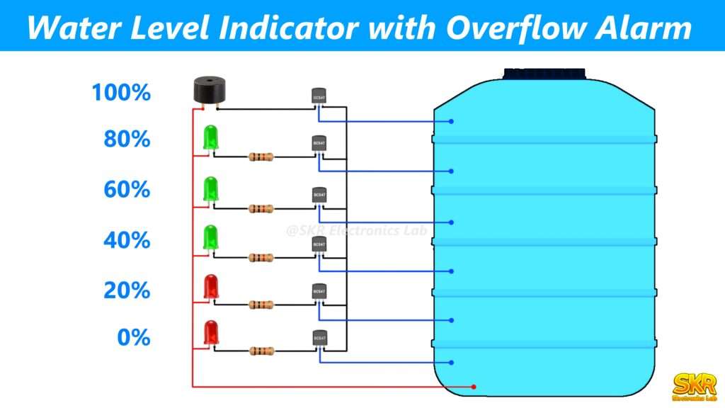
Are you tired of constantly checking your water tank and worrying about overflow? A water level indicator with an overflow alarm may be the solution you need.This device automatically monitors your water level and alerts you before it overflows, It helps conserve water and relieves you from constantly checking the tank.
In this blog post, we’ll explain how this device works, why it’s useful, and how you can easily make it at your home. Say goodbye to overflow worries and hello to a more efficient way to manage your water usage!
Components Required
Circuit Diagram
How the circuit works
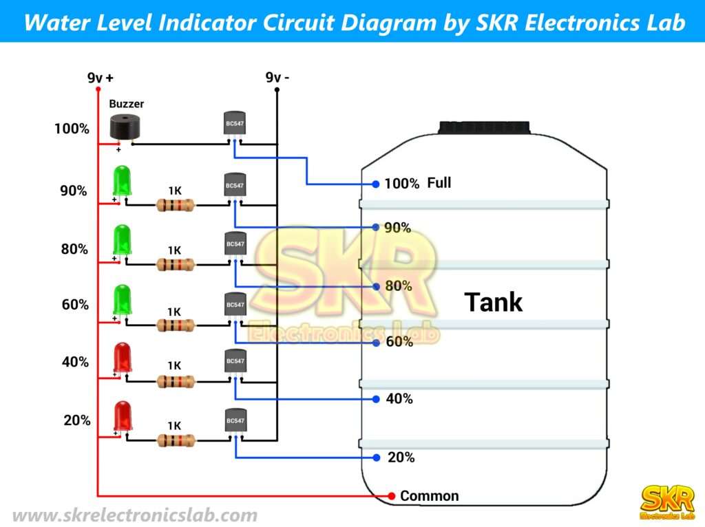
The main component of the circuit is the BC547 transistor. Let’s give you a little idea about transistors, A transistor is a semiconductor device that can act as a switch or amplifier. It has three pins: emitter base and collector. If we supply a small amount of current to the base pin of the transistor, then a large amount of current flows from the emitter to the collector pin. Transistors are generally of two types – NPN and PNP.
In our circuit we have used BC547 transistor which is an NPN type transistor. The base pin of the transistor is connected to the ground (Negative supply) And we have connected the negative pin of the LED and buzzer with the collector pin through 1K resistor. This 1K resistor will protect the LEDs from being damaged by high current. We have connected the positive pins of the LED and buzzer to the supply positive. So now if we apply a small amount of voltage to the base pin of the transistor, then the LEDs and the buzzer will turn on.
We can divide the main circuit into 6 parts and every part is the same except for the buzzer part. We have not used any resistor in the buzzer part because we want the maximum current to flow through the buzzer and the rest of the part is the same as the others. So now if we want to turn on the LED or buzzer of any part, we have to give positive supply to the base pin of the transistor of that part. Now we will connect the base pins of each part of the transistor with each level of the tank, and at the lowest level we will connect the positive supply. As a result, whenever the water touches a level, the LED or buzzer attached to that level will turn on. This is how the circuit works. I know I didn’t explain you very well, I tried my best to make it as simple as possible. So if you have any doubt about this circuit then you can comment or write your doubt on contact us page, I will definitely help you. Thank you for reading the post and have a nice day.