Introduction
Guys, does the water tank overflow in your house and waste a lot of water? So, in today’s tutorial, I will teach you how to make a device that will let you know before your tank water overflows through an announcement alert. There are many tutorials online where they have used a buzzer instead of a voice alert. But in today’s tutorial, I will show you the device that will give a voice alert after the water tank overflows. So, let’s see what components we need to make the device.
Components Required
Tools Required
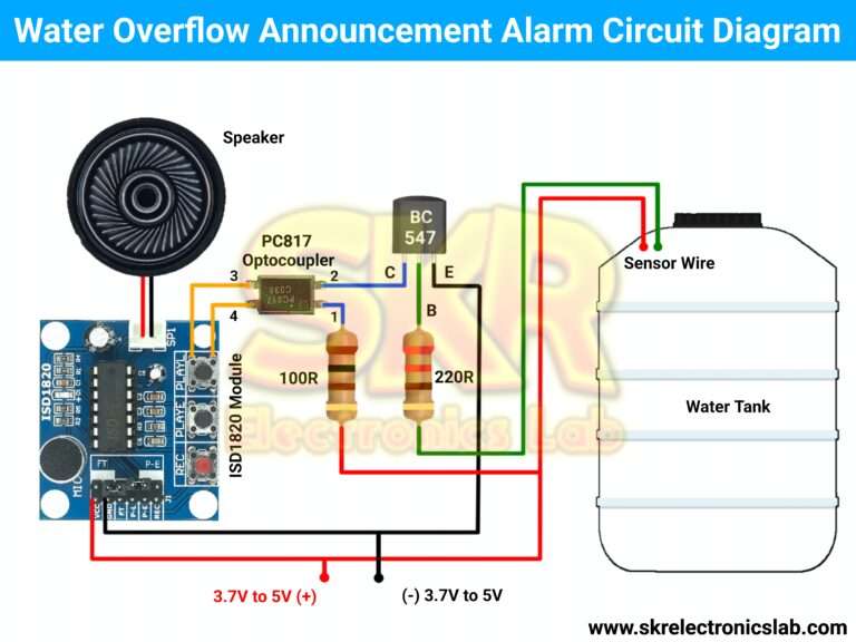
Circuit Diagram
Working Explanation
To understand the working principle of this circuit we have to divide it into two parts, one is the audio announcement part and the other is the sensor or detection part.
Audio Announcement Part
The audio part is the ISD1820 voice recorder module, which can record 10 seconds of audio by the built-in microphone and playback the recorded audio. This module required a 3V to 5V power supply to run. This module has 3 push buttons REC, PLAYE, and PLAYL these three buttons have three different functions.
"REC" or Record Button
Pressing this button will start the audio recording, after releasing the button it will stop the recording. The recording will stop automatically after 10 seconds.
PLAYE or Play Edge Button
Pressing this button will play the entire audio once.
PLAYL or Play Level Button
This button is also used to play audio but, its function is slightly different from PLAYE, pressing this button will play the recorded audio until the button is released. We will use this button to announce the overflow.
So you need to record the audio message that you want to hear after the overflow.
Sensor or Detection Part
Sensor part or detection part, it will detect the water overflow. The main component of this circuit is the BC547 NPN transistor.
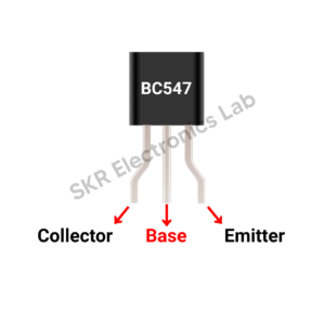
It has three pins – Base, Collector, and Emitter. Since it is an NPN-type transistor, if we apply a small amount of positive current to its base pin, the transistor will turn on and current will flow from the emitter to the collector pin.
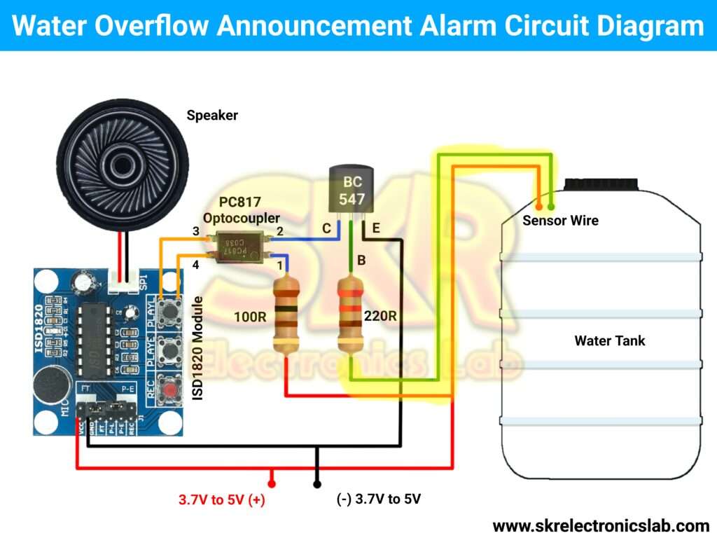
In the circuit we can see that two sensor wires coming from the tank. One is connected to the base pin of the transistor via a 220 ohm resistor and the other wire is connected to the positive supply. So when the water touches these two wires in the tank the transistor will turn on and current will start flow from the emitter pin to the collector pin.
Now we have to control the PLAYL button of ISD1820 Voice Recorder Module through this transistor, which is not possible to do directly. So we have to use a component which is optocoupler.

An optocoupler is an electronic component that can transfer electrical signal from one circuit to another circuit but there will be no physical connection. It has four terminals – Anode, Cathode, Emitter, and Collector. Inside the Optocopuler a LED is connected to the anode and cathode pin and a photosensitive device is connected to the Emitter and Collector pin. If we connect the anode and cathode pin to the supply the LED will start emitting infrared light which will turn on the photosensitive device and then the current can pass from the emitter to the collector of the Optocopuler.
In our overflow alarm circuit, we have connected the emitter and the collector pin of the optocoupler with the PLAYL button of the ISD1820 voice recorder module, and the anode & cathode pin of the optocoupler are connected to the positive supply and transistor collector pin respectively.
So when the water in the touches the sensor wire, the transistor will turn on and the transistor will turn on the optocoupler and the optocoupler will trigger the Play L button. Then the audio recorded in the module will start playing. This is how the circuit works.